Attributes
| Brand | AFCON |
|---|---|
| Figure Number | AF772 |
| Material | Steel |
| Finish | Plain, Electro Galvanized |
| Filter Attributes | {"Brand":"AFCON","Figure Number":"AF772","Material":"Steel","Finish":"Plain, Electro Galvanized","Pipe Type":"Steel","Pipe Connection":"Seismic Brace","Solutions":"Mechanical & Plumbing Systems, Commercial & Residential, Data Centers, Industrial, Energy & Power, Mining, Fire Protection, Oil & Gas, Water & Wastewater","Size Range":"Beam Widths: 4\" through 15\", Flange Thickness: 3/8\" through 1 1/4\"","Service":"Designed to rigidly brace piping systems subjected to horizontal seismic loads. May also be installed to brace piping systems subjected to vertical seismic loads. For vertical load capacities, reference OSHPD OPM-0351-13.","Approvals":"cULus Listed (UL 203a) and FM Approved (FM 1950-10 & FM 1950-13). OSHPD Pre-Approved (OPM-0351-13 and OPA-2804-10). Complies with the hanging and bracing requirements listed in NFPA 13.","Features":"Field adjustable to fit a wide range of beams.; Centers the Fig. AF771 below the beam.","Installation Instructions":"Move both c-clamps until they reach the outside of the slots.; Place the adjustable steel beam attachment on the underside of the beam and adjust the c-clamps until the contact the outside edges of the beam flange. Hand tighten the c-clamp bolts.; Torque each shear off set screw until the head shears off.; Torque each c-clamp bolt to 55ft-lbs to secure the channel to the underside of the beam.; Install the Fig. AF771 to the center mounting bolt. Installation angle determined by the brace angle of the AF771 and brace pipe.; Fire Protection applications shall also be installed per the requirements of NFPA 13 and local codes.","Ordering":"Specify type, length, figure number, finish and description.","Category":"Support Systems > Seismic Bracing > Seismic Braces","Equivalent Products":"Anvil 772; AFCON 086; Caddy CSBIB, CSBBC; Tolco 800"} |
| Equivalent Products | {"manufacturer":"Anvil","productNumber":"772"}, {"manufacturer":"AFCON","productNumber":"086"}, {"manufacturer":"Caddy","productNumber":"CSBIB, CSBBC"}, {"manufacturer":"Tolco","productNumber":"800"} |
| Upc Codes | {"0":"690291233111","1":"690291233142","2":"690291233159","3":"690291233166","4":"690291233180","5":"690291233197","6":"690291233203","7":"690291243011","8":"690291243035","9":"690291243042","10":"690291243059","11":"690291243073","12":"690291243080","13":"690291243097","14":"69029123311","15":"69029123314","16":"69029123315","17":"69029123316","18":"66242850489","19":"69029123318","20":"69029123319","21":"69029123320","26":"662428504890","30":"69029124301","31":"69029124303","32":"69029124304","33":"69029124305","34":"66242850488","35":"69029124307","36":"69029124308","37":"69029124309","42":"662428504883"} |
| Algolia Submittal | /resource/AF772 Adjustable Steel Beam Attachment Submittal |
Description
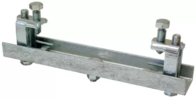
Size Range: Beam Widths: 4" through 15", Flange Thickness: 3/8" through 1 1/4" Material: Carbon Steel Finish: Plain or Electro-Galvanized per ASTM B633 Service: Designed to rigidly brace piping systems subjected to horizontal seismic loads. May also be installed to brace piping systems subjected to vertical seismic loads. For vertical load capacities, reference OSHPD OPM-0351-13. Approvals: cULus Listed (UL 203a) and FM Approved (FM 1950-10 & FM 1950-13). OSHPD Pre-Approved (OPM-0351-13 and OPA-2804-10). Complies with the hanging and bracing requirements listed in NFPA 13. Features: Field adjustable to fit a wide range of beams. Centers the Fig. AF771 below the beam. Installation Instructions: Move both c-clamps until they reach the outside of the slots. Place the adjustable steel beam attachment on the underside of the beam and adjust the c-clamps until the contact the outside edges of the beam flange. Hand tighten the c-clamp bolts. Torque each shear off set screw until the head shears off. Torque each c-clamp bolt to 55ft-lbs to secure the channel to the underside of the beam. Install the Fig. AF771 to the center mounting bolt. Installation angle determined by the brace angle of the AF771 and brace pipe. Fire Protection applications shall also be installed per the requirements of NFPA 13 and local codes. Ordering: Specify type, length, figure number, finish and description.
Variations (16)
0500602008
| Code System | ASC Item Number |
|---|
0500602016
| Code System | ASC Item Number |
|---|
0500602024
| Code System | ASC Item Number |
|---|
0500602032
| Code System | ASC Item Number |
|---|
0500602115
| Code System | ASC Item Number |
|---|
0500602123
| Code System | ASC Item Number |
|---|
0500602131
| Code System | ASC Item Number |
|---|
0500608005
| Code System | ASC Item Number |
|---|
0500608013
| Code System | ASC Item Number |
|---|
0500608021
| Code System | ASC Item Number |
|---|
0500608039
| Code System | ASC Item Number |
|---|
0500608112
| Code System | ASC Item Number |
|---|
0500608120
| Code System | ASC Item Number |
|---|
0500608138
| Code System | ASC Item Number |
|---|
0500602107
| Code System | Anvil 10-Digit Code (legacy) |
|---|
0500608104
| Code System | Anvil 10-Digit Code (legacy) |
|---|
Specifications
| Brand | AFCON |
|---|---|
| Figure Number | AF772 |
| Material | Steel |
| Finish | Plain, Electro Galvanized |
| Pipe Type | Steel |
| Pipe Connection | Seismic Brace |
| Solutions | Mechanical & Plumbing Systems, Commercial & Residential, Data Centers, Industrial, Energy & Power, Mining, Fire Protection, Oil & Gas, Water & Wastewater |
| Size Range | Beam Widths: 4" through 15", Flange Thickness: 3/8" through 1 1/4" |
| Service | Designed to rigidly brace piping systems subjected to horizontal seismic loads. May also be installed to brace piping systems subjected to vertical seismic loads. For vertical load capacities, reference OSHPD OPM-0351-13. |
| Approvals | cULus Listed (UL 203a) and FM Approved (FM 1950-10 & FM 1950-13). OSHPD Pre-Approved (OPM-0351-13 and OPA-2804-10). Complies with the hanging and bracing requirements listed in NFPA 13. |
| Features | Field adjustable to fit a wide range of beams.; Centers the Fig. AF771 below the beam. |
| Installation Instructions | Move both c-clamps until they reach the outside of the slots.; Place the adjustable steel beam attachment on the underside of the beam and adjust the c-clamps until the contact the outside edges of the beam flange. Hand tighten the c-clamp bolts.; Torque each shear off set screw until the head shears off.; Torque each c-clamp bolt to 55ft-lbs to secure the channel to the underside of the beam.; Install the Fig. AF771 to the center mounting bolt. Installation angle determined by the brace angle of the AF771 and brace pipe.; Fire Protection applications shall also be installed per the requirements of NFPA 13 and local codes. |
| Ordering | Specify type, length, figure number, finish and description. |
| Category | Support Systems > Seismic Bracing > Seismic Braces |
| Equivalent Products | Anvil 772; AFCON 086; Caddy CSBIB, CSBBC; Tolco 800 |
PDF Documents
[Product Data Sheets] AF772 Adjustable Steel Beam Attachment Submittal
Open PDF
[Product Resources] Anvil Pipe Hangers & Supports Submittal Catalog
Open PDF
[Product Resources] Anvil-Strut™ Metal Framing Product and H-Block Catalog
Open PDF
[Approvals and Certifications] Anvil Pipe Hangers - Henderson Plant - Certificate of Compliance
Open PDF